
By: Isaack Karanja, Senior Solution Architect
In this post, Senior Solution Architect Isaack Karanja lays out the process of how to build and configure a VMware environment including at a minimum vRealize Automation and NSX.
Please see sections below:
Section 1: Identifying the Business Need
Section 2: Understanding the Solution Architecture
Section 3: Solution Implementation
Section 4: Create the Network Profiles
Section 5: Security Groups and Security Policies
Section 6: Create a Multi-Machine Blueprint
Section 7: Mapping Networks to the Multi-Machine Blueprint
Section 8: Load Balancing for the Web Tier
Section 9: Publish Application to VRA
Section 10: Architecture Review
Please feel free to contact us if you’d like more information on this post at (866) 898-9506 or [email protected].
Section 1: Identifying the Business Need
I recently worked with a client who needed to deliver an application to his internal consumers. The client was putting together an application that had three typical tiers: Web, Application and Database. The web tier servers required to sit behind load balancers with VIPs. The web apps also required to have external reachability from the outside network. The application servers needed the ability to initiate communication with the outside world but no connections could be initiated from outside the network to the app servers. The databases were not allowed to talk to any servers other than the application servers.
The resulting application looked like this:
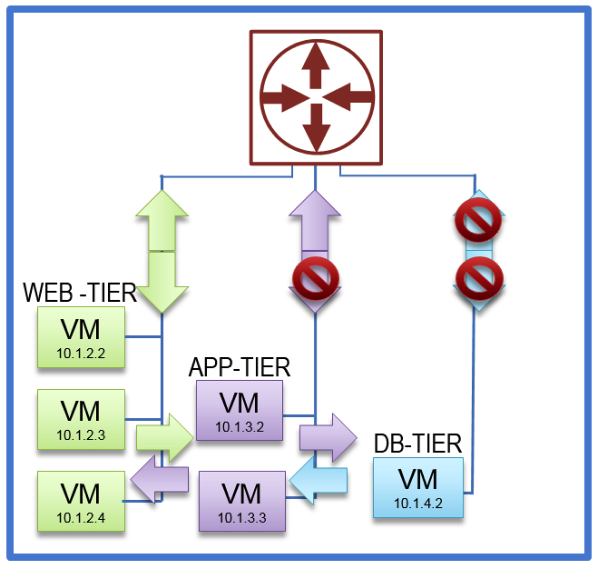
Click on the photo for a larger view.
The client was also exploring the paradigm of being able to build once and deploy many. The idea was to start development of one application, then move it to test & QA, and then production without having to deploy a new application and only make changes to the IP addresses external to the application, as shown below:

Click on the photo for a larger view.
Section 2: Understanding the Solution Architecture
The solution involved VMware vRealize Automation (VRA) with NSX. The client already uses VRA, so all they need to add is NSX. Using VRA, you can orchestrate network provisioning during the deployment of an application. There are countless features that come with VRA and NSX, but this blog post will focus on the features that are used to address this particular client’s business need.
As I prepared to assist this client, I found a good amount of documentation on how to get started with VRA and NSX, but not a lot of information on how to configure VRA to deploy various network topologies using NSX. If someone is looking to get official training implementing VRA with NSX, you can get this from the VMware class “VMware NSX: Troubleshooting and Operations.” From the course outline, VRA and NSX are covered on the last session of the class.
There are three different types of network profiles that VRA can be configured with. Combining these network profiles, you can configure quite a number of topologies.
The network profiles are:
- External Profile – This contain a range of static IP addresses available on the external network
- Routed Profile – This contain the range of IP addresses that are routable
- NATed Profile – Under the NATed profile you can configure either
- One to One – Maps one external address to one internal address (DNAT)
- One to Many – Maps one external address to many shared internal addresses (SNAT)
- Private Profile – These are internal networks that have no connections to the external network
Section 3: Solution Implementation
To implement the solution, the External Network profiles, 1:1, 1:Many, NAT network profile and private network VRA, network profiles are required. To configure the network profiles through VRA, a multi-machine blueprint is also required to map the network profiles to a virtual machine (VM) application.
Here the steps to configure the network profiles:
The instructions below assume that VRA and NSX have been installed and configured. Familiarity of VRA, VCenter and NSX GUI is also assumed. The following steps will be taken to create the final solution:
- Create the Network Profiles
- Create Security Groups
- Create Security Policies
- Create a Multi-Machine Blueprint
- Map Application to network in Multi-machine blueprint
- Configure Load Balancers for the Web Tier
- Publish Multi-Machine Blueprint in VRA
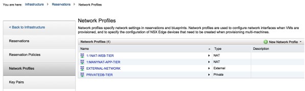
Section 4: Create the Network Profiles
1. Under the vRealize Automation GUI, you create the network profile under the
Infrastructure → Reservations → Network Profiles tab
I have already created my external Network profile titled EXTERNAL-NETWORK as shown below. This network has reserved IP addresses that are routable from my organization’s external networks.
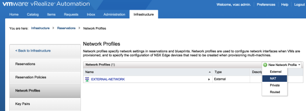
Click on the photo for a larger view.
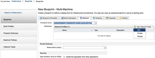
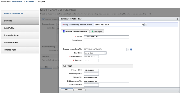
2. Create a 1:1 NAT network profile as shown below:
The NAT’ed profile is attached to the EXTERNAL -NETWORK profile. The NAT profiles are used to setup the SNAT and DNAT rules that will translate the EXTERNAL-NETWORK IP addresses to their corresponding internal IP addresses. The 1:1 NAT network profiles are created as shown below:
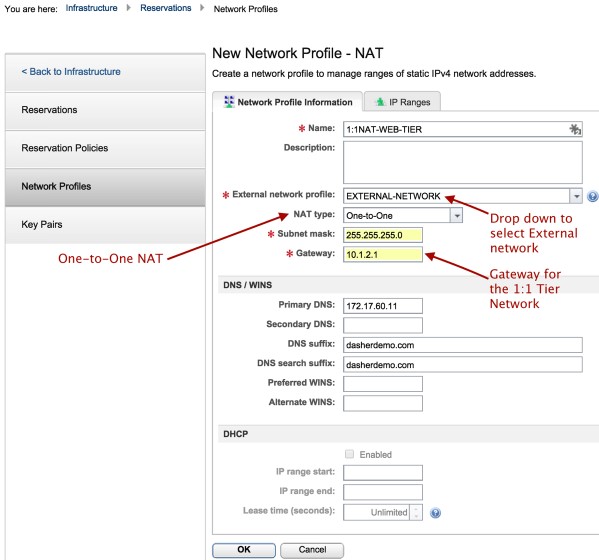
Click on the photo for a larger view.
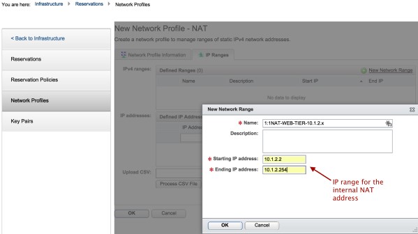
Click on the photo for a larger view.
3. In the same way, create a 1:MANY NAT network profile and private profile.
Click on the photo for a larger view.
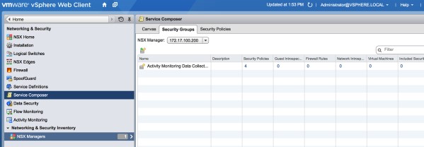
Section 5: Security Groups and Security Policies
In the three tier application, it was required that the databases’ virtual machines would not be able to communicate with anything else other than the application tier virtual machines. To enforce this requirement, we used NSX security groups.
Simply put, security groups are mechanisms that allow you to group objects. These objects can be, for example, virtual machines, networks authenticated users, etc. Security groups are powerful in that they can make use of user defined tags to group objects.
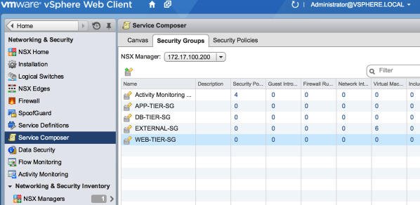
Security groups are administered in VMware in the Networking and Security section under service composer.
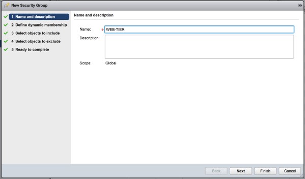
1. Create a new Security Group and give it the name WEB-TIER-SG.
Click on the photo for a larger view.
Click on the photo for a larger view.
2. You can use either dynamic or static membership rules. Security group memberships are rules that are used to determine what entity will be included in the security group. I am going to create three dynamic membership rules that will select virtual machines with names that start with a particular prefix, for example web as shown below:
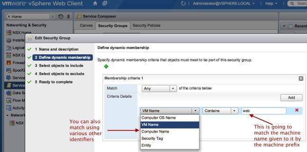
Click on the photo for a larger view.
3. As shown below, the blueprints are pre-configured to name the machines with names that identify the tier they belong to:
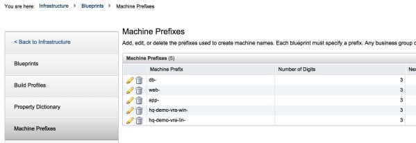
Click on the photo for a larger view.
4. I am also going to create an EXTERNAL-SECURITY-GROUP static membership rule to select the external network distributed port group as an object in the security group as shown below:
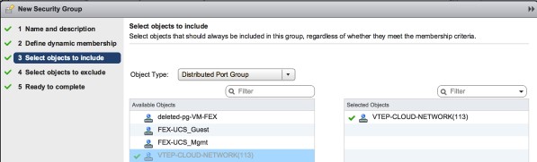
Click on the photo for a larger view.
Click on the photo for a larger view.
Security Policies
Security Policies are rules that define how traffic flows between security groups. The concept of security groups and security policies is much simpler than the use of traditional ACLs.
1. Create a Security Policy called WEB-Tier-Allow:
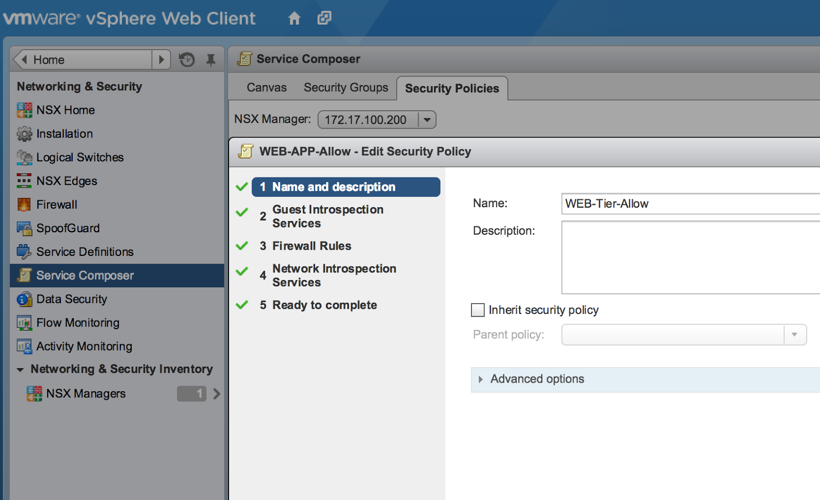
Click on the photo for a larger view.
2. Under the firewall rules tab, change the source security group to web tier with the enforcement to allow traffic. This policy will allow traffic from the web-tier to any security group that it is associated with:
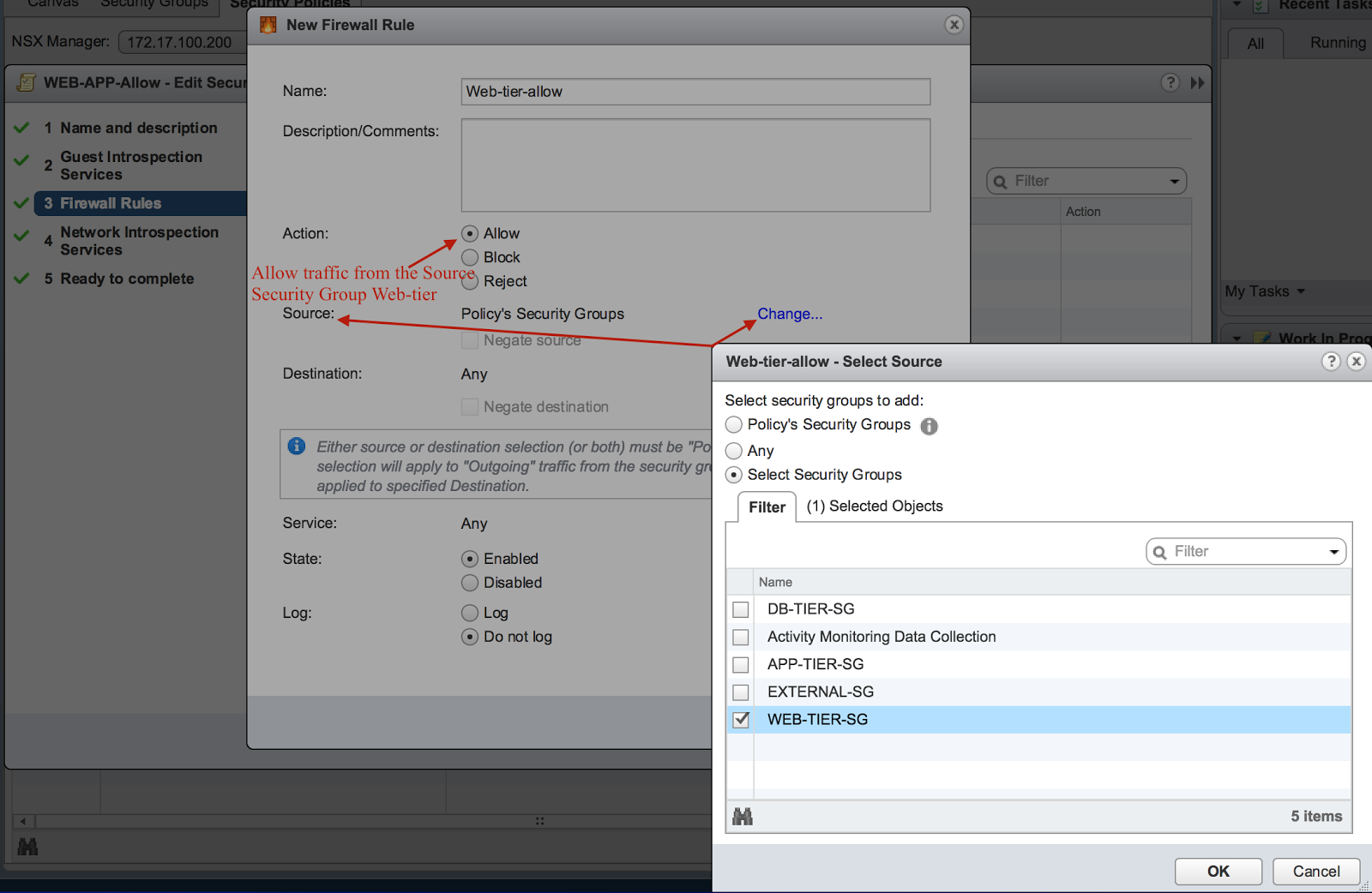
Click on the photo for a larger view.
3. Under each of the security groups, edit and associate a security policy with each of the security groups:
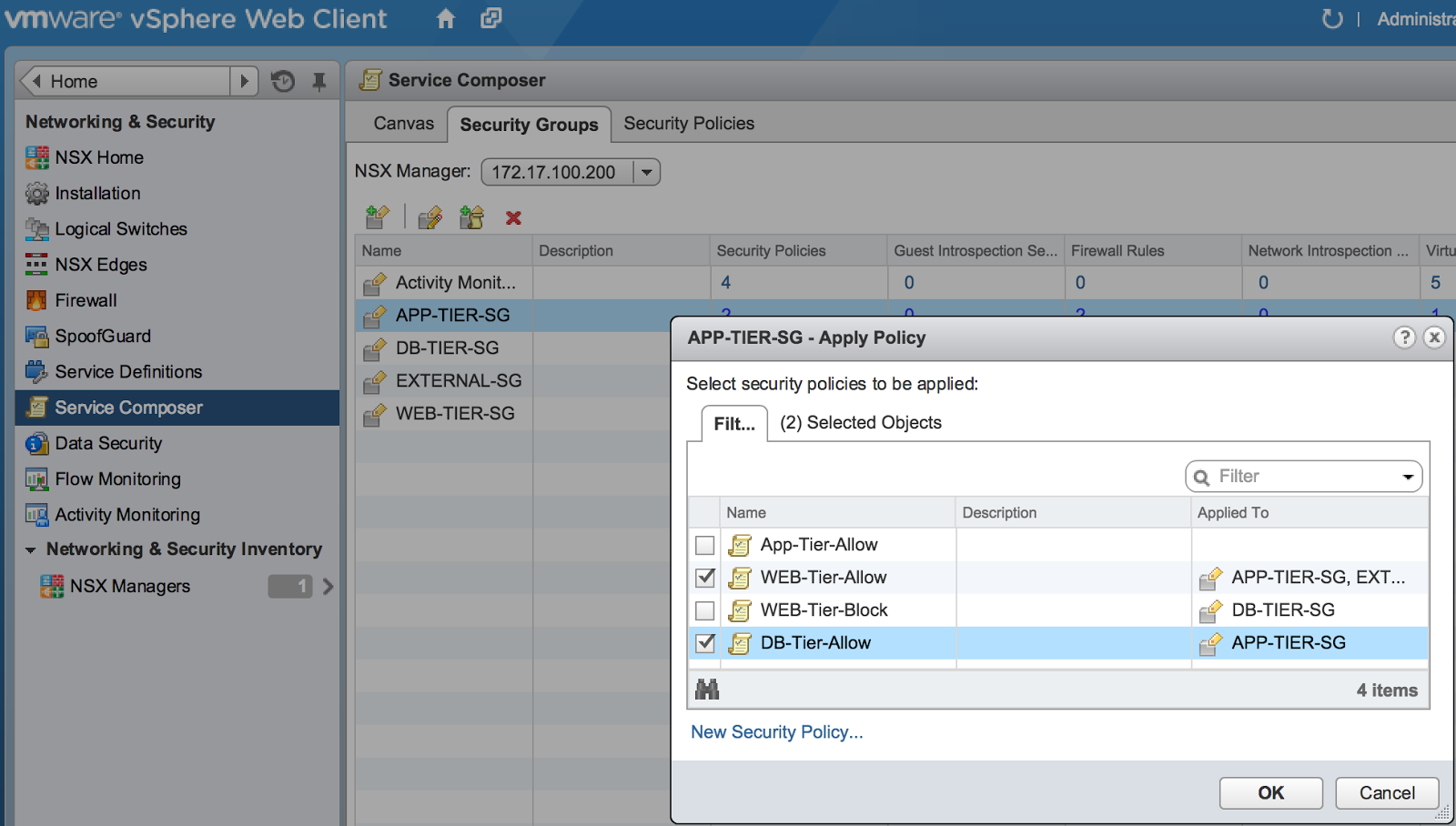
Click on the photo for a larger view.
In the configuration above, a firewall rule is used in the security policy that allows traffic to pass between a specified security group and any other security group associated with a particular security policy. Here we see that the app-security policy allows all source traffic from the app security group to flow. This app-security policy is then associated with the DB and WEB security group. This configuration will allow traffic from the app security group to pass between the DB and WEB security groups.
Section 6: Create a Multi-Machine Blueprint
To map the network profiles to a blueprint, we need to use a multi-machine blueprint. I have already pre-created a three windows blueprint that is going to be used as the base blueprint for the web, app and DB tiers as shown below:
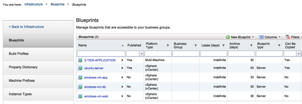
Click on the photo for a larger view.
1. Create a multi-machine blueprint, in the configuration below. The multi-machine blueprint is called 3TIER-Application:
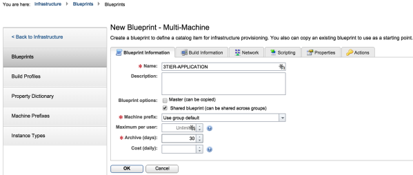
Click on the photo for a larger view.
2. Under the Build Information TAB, select the pre-configured blueprint to add to the multi-machine blueprint:
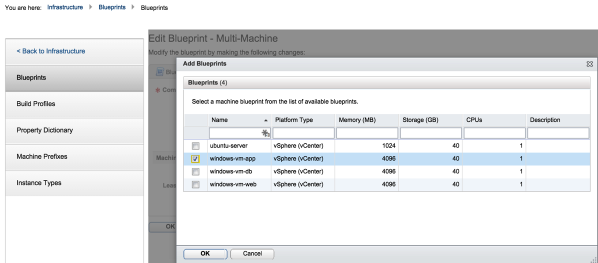
Click on the photo for a larger view.
3. Rename the blueprints to match the three tiers. You can also configure the startup and shutdown order and select the number of servers required in that particular tier:
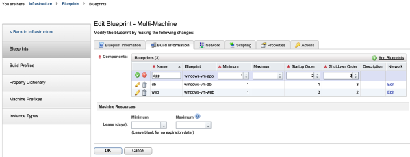
Click on the photo for a larger view.
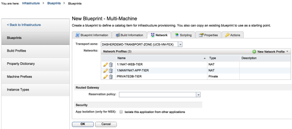
Section 7: Mapping Networks to the Multi-Machine Blueprint
When working with NSX, use of multi-machine blueprints is required to associate virtual machines in a blueprint with their appropriate networks. To configure the virtual machines, log into VRA and navigate to the Network TAB in the Blueprints section.
1. Add the networks to the multi-machine blueprint:
Click on the photo for a larger view.
Click on the photo for a larger view.
2. Repeat for 1:Many and DB Network profiles and the resulting configuration will look as shown below:
Click on the photo for a larger view.
3. Edit each of the virtual machines network and add a network adapter. Attach the adapter to the appropriate network profile:
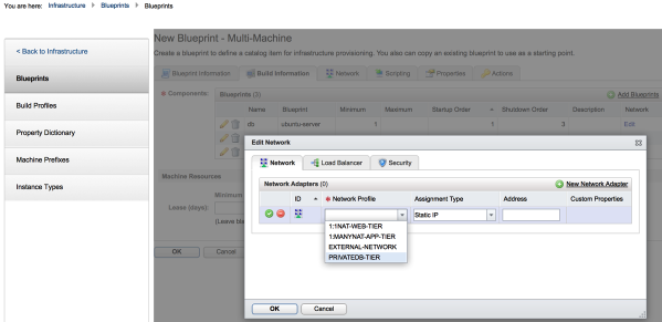
Click on the photo for a larger view.
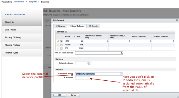
Section 8: Load Balancing for the Web Tier
NSX provides the ability to configure distributed load balancers. We will configure load balancers for the WEB blueprints, these will be configured to load balance the HTTP traffic.
- After adding the network adapter and mapping it to the appropriate tier, select the load balancing tab and select http.
- For the web tier, we need to NAT to an External IP so we select the external network profile.
- We do not manually type in the Load Balancer VIP since this is assigned automatically from the External-Network IP pool
Click on the photo for a larger view.
4. Under the security tab, we will associate each blueprint with the appropriate security group. Under the security tab, select the appropriate security groups that were created earlier:
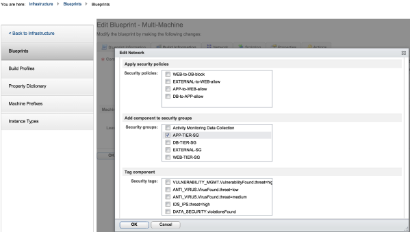
Click on the photo for a larger view.
Section 9: Publish Application to VRA
1. The Final Step is to publish the application to VRA.
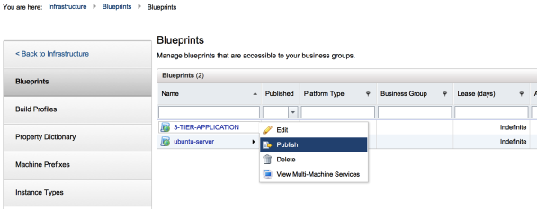
Click on the photo for a larger view.
Click on the photo for a larger view.
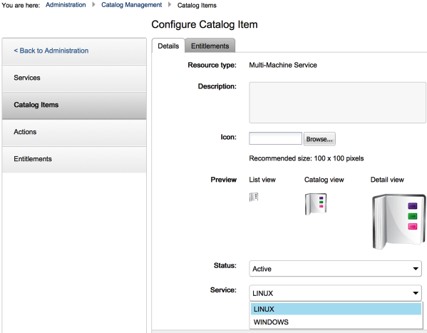
2. The application is now ready to be consumed by the users from the catalog.
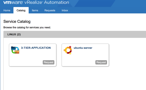
Click on the photo for a larger view.
Section 10: Architecture Review
Once the application is requested by a user the following components will be deployed: NSX Edge and Logical Switches that connect the three tiers.
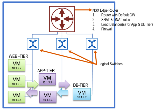
Click on the photo for a larger view.
In VCenter you can see the DNAT and SNAT rules that are created on the NSX Edge Device. The WEB tier gets 1:1 NAT and the APP tier gets 1:MANY NAT. A load balancer is configured to balance http traffic across the three web servers.
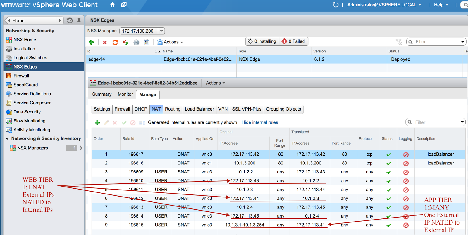
Click on the photo for a larger view.
When examining the firewall rules that are created by Security Policies that were applied to the Security Groups, we see that WEB tier is not allowed to talk to the DB tier. All other tiers can talk to each other. The default NSX firewall rule is to block traffic.
One thing to be noted is that NSX security policies and security groups can be associated with third party security appliances from vendors such as Palo Alto Networks. This is configured under the Partner Security Services tab.
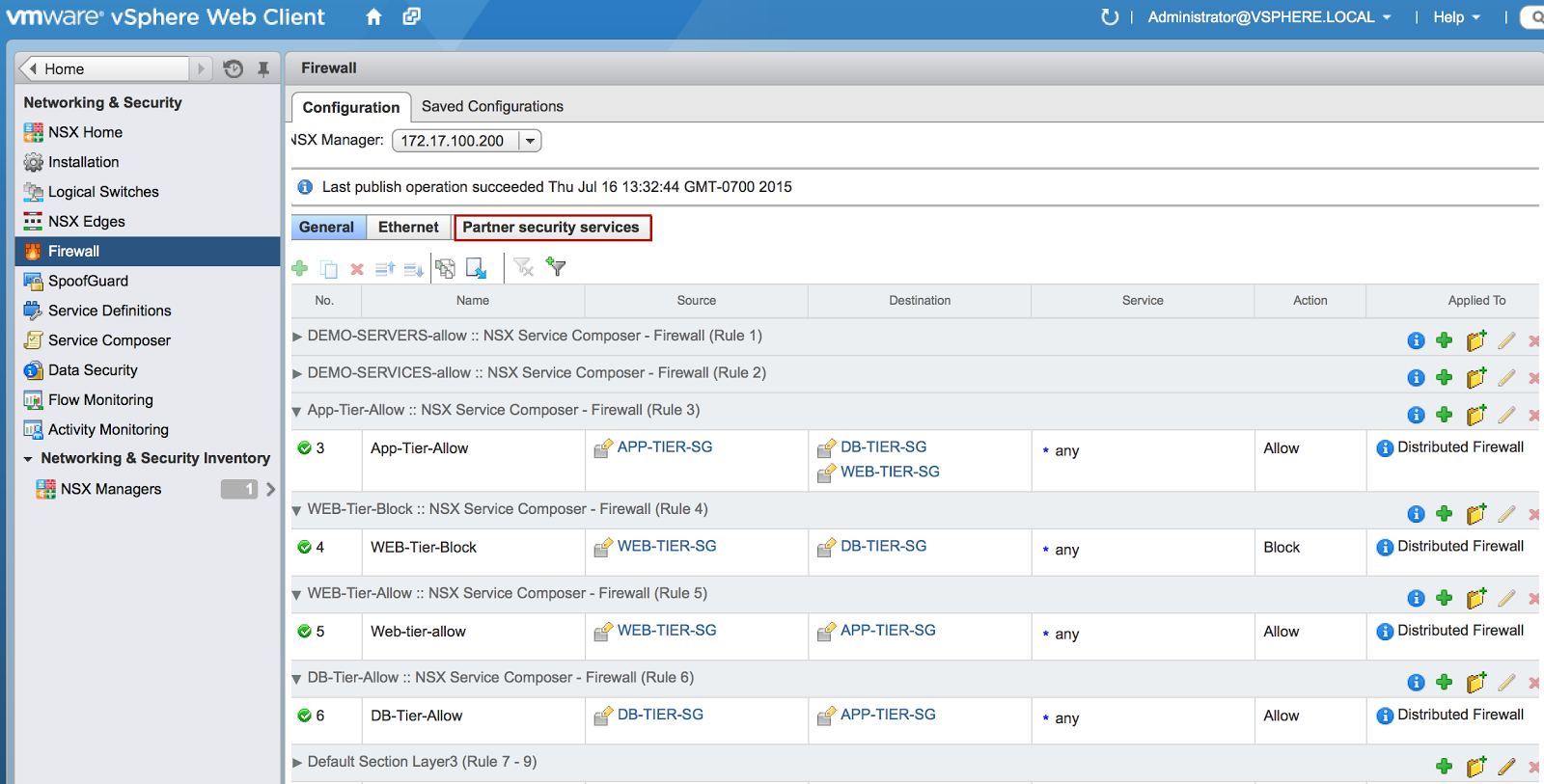
Click on the photo for a larger view.
Please feel free to contact us if you’d like more information on this post at (866) 898-9506 or [email protected].