
By Bobby Glover, Solution Architect & Mitchell Hurd, Network Deployment Engineer
HP Intelligent Resilient Framework (IRF)
HP Intelligent Resilient Framework (IRF) is a technology that was originally developed by 3Com and released in 2003 as XRN (eXpandable Resilient Networking). When HP acquired 3Com in April 2010, HP renamed the technology to IRF. Although IRF technology is proprietary to Hewlett Packard Enterprise (HPE) switches running Comware OS, there are similar technologies available from Cisco and Juniper Networks.
IRF is essentially a virtual stacking technology that allows multiple switches to be managed and operate as a single large virtual switch, called an IRF fabric. This allows IT departments to cut down the complexity of network management. With IRF, a group of up to nine switches can be managed as a single logical device with one management IP address. Tedious network management tasks such as provisioning multiple switch ports are simplified and streamlined. Ports spread across multiples switches can be provisioned from the same management interfaces on what is presented to the network manager as a single “virtual switch”. As noted before, one IRF domain can encompass up to nine switches, with the added capability that physical link distance between switches can be up to 70km, meaning one management interface can manage switches in multiple locations.
IRF distributes the entire stack configuration to all IRF domain members. In the event of a switch or link failure, this allows the IRF domain to re-converge quickly and improve overall network uptime. In addition, IRF effectively and efficiently replaces Spanning Tree Protocol (STP). Some of the limitations of STP, such as backup links wasting resources (switch ports, potential switch-to-switch throughput) are eliminated with IRF.
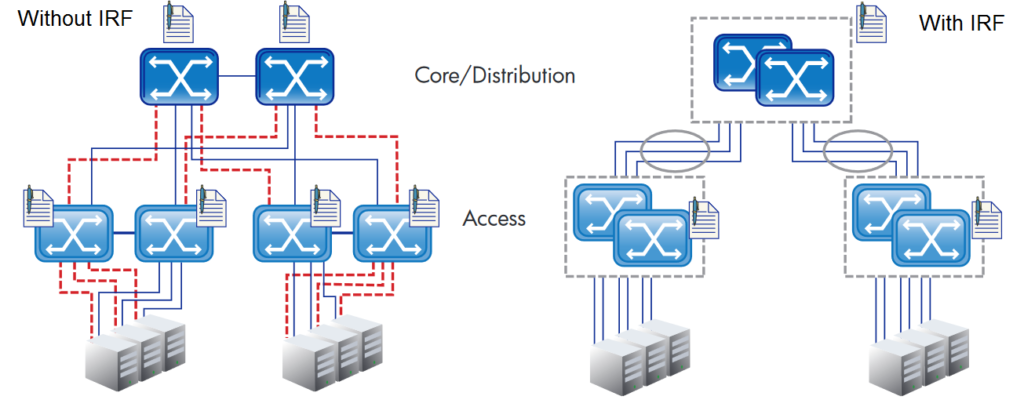
See the diagram below. With a traditional network topology, each switch must be configured independently and Spanning Tree Protocol must be configured on redundant links in order to prevent network loops, reducing available bandwidth by half. However with an IRF topology, switch configuration is centralized to a single management IP for each IRF fabric. Additionally, port aggregation can be enabled across multiple switches in the same IRF fabric, eliminating the need for STP altogether. This allows full utilization of all links, increasing available bandwidth.
An IRF fabric can be configured in either a daisy chain or ring topology as shown below.
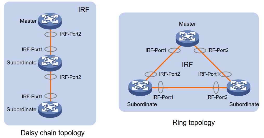
In a ring topology, the failure of one IRF link does not cause the IRF fabric to split as in a daisy chain topology. Rather, the IRF fabric changes to a daisy chain topology without interrupting network services.
Configuration Example
So how do we configure it? Below is a configuration example for an HPE 5130 switch. Similar commands would need to be configured on each of the switches that will form the IRF fabric. The CLI commands are listed in bold italics. Check out 5130 Configuration Guide, written in 2015.
Start by setting a member number and priority for each switch. Each switch must have a different member number. Member priority determines the possibility of a member device to be elected the master. A member with higher priority is more likely to be elected the master. The default member priority is 1.
irf member 1 priority 32
Next select the physical ports on the switch that you would like to use for the IRF link between switches. You can use between 1 and 4 physical ports for a single IRF link between devices. Before assigning the ports to IRF they must be shut down.
int range ten-gig 1/0/45 to ten-gig 1/0/48
shutdown
Quit
Next assign the physical ports to the IRF link. In this example, we will have the switch connecting to two other switches with redundant links.
irf-port 1/1
port group interface ten-gig 1/0/45
port group interface ten-gig 1/0/46
irf-port 1/2
port group interface ten-gig 1/0/47
port group interface ten-gig 1/0/48
Quit
Next turn the ports back on
int range ten-gig 1/0/45 to ten-gig 1/0/48
undo shutdown
Quit
Save your config now. The final command we will execute will activate IRF and in specific cases may cause the device to reboot without saving the config, so we always recommend manually saving the config.
save
Finally, it is time to enable IRF!
irf-port-configuration active
After this step is performed, the state of the IRF port changes to UP, the member devices automatically elect a master, and the subordinate devices automatically reboot. If the subordinate switches do not automatically reboot after entering the above command, we recommend that you reboot them manually.
Reboot
After the reboot, if all switches have IRF configured correctly, they will form the IRF fabric and can be managed from the IP address of the IRF master which we specified with the priority command in step 1.
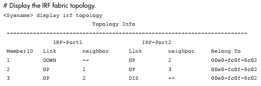
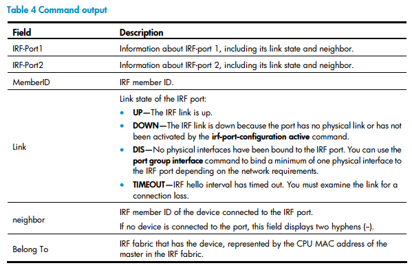
Confirm that the IRF fabric is working with these commands:
Display IRF
Display IRF Topology
That’s it! Now you can enjoy the increased network resilience, performance, availability, and reduced operational complexity that IRF brings to your organization.