
Datacenter Electrical Power – An Overview
By Bill Jones, Enterprise Architect
Disclaimer
I am not a licensed electrician. Please consult with a licensed, bonded electrician or master electrician in your local area for assistance with electrical circuit or electrical system design.
Introduction
My father was a professional engineer and a master electrician. When I was young, I asked him about a strange looking item on his keyring. He explained it was a stamp which bore his seal as a professional engineer. When he approved a design, he would stamp the schematic. If he had missed a flaw in the design, he was responsible for any damage it caused. It was one of my first lessons in electrical safety.
As an IT administrator, I would frequently call my father when I had questions about datacenter power. He was proud of my career, and at the same time, I think he really enjoyed the opportunity to share his career with me in this way. Those conversations are some of my favorite memories, especially the ones where he tried to remain patient while repeating himself for the umpteenth time. Those conversations helped me to have more effective conversations with facilities management and with electricians and master electricians over the years.
And so, in this blog post, I’d like to share with you some of the basics of what I learned from my dad about commercial electrical power over the years. My hope is that it can help you have more effective conversations with facilities staff and with licensed, bonded electricians.
AC vs. DC
At a basic level, almost every adult in an industrialized nation understands the basics of direct current (DC). Batteries provide DC electricity. Current flows from one end (or terminal) of the battery to the other. When the batter stops working, recycle the old battery and buy a new one. This works with a flashlight, a video game controller, and most automobile.
Whether the power source is a battery or a charger for a laptop, the principle for direct current is the same. Electrons flow from the negative terminal, through the circuit, and into the positive terminal. The flow of electrons is called a current, and with DC, the current flow is in only one direction – from negative to positive.
Alternating Current (AC) is different. With AC circuits, the current flow reverses multiple times per second. For example, in the United States, most AC circuits are 60 hertz (Hz); in most of Europe, AC is 50Hz. A hertz is a “per second.” So, 60Hz is 60 times per second.
One of the major benefits to AC is that it can deliver power to homes and businesses which are much further away from the power station than could be done with DC. However, when we look at things we use within a datacenter (computers, network switches, etc.), their internal components usually require DC power. The power supplies in these devices can convert the AC input power to DC.
Volts, Amps, Volt-amps, and Watts
Before we dive too deeply into the details, let’s review a few key terms.
Volts
Voltage is a measurement of the potential difference between two points on an electrical circuit. There must always be two points. For example, in this blog post we will cover circuits where voltage is measured hot-to-neutral and others where it is measured hot-to-hot. The symbol for volts is V.
Amps
Amperes (amps) are a measurement of electrical current. Specifically, one amp is one coulomb per second, and one coulomb is an electrical charge which is equivalent to 6.2415090744×10¹⁸ electrons. The symbol for amps is A.
Volt-Amps
Volt-Amperes are a measurement of supplied electrical power. Volt-amps are used when measuring electrical power supplied by circuits, PDUs, etc. and are calculated by multiplying volts and amps. The symbol for volt-amps is VA. Please compare with watts.
Watts
Watts are a measurement of electrical power consumed. Watts are used when measuring the power consumed by electrical devices (servers, network switches, monitors, laptop power supplies, etc.). Watts are calculated by multiplying volts and amps. The symbol for watts is W. Please compare with volt-amps.
Circuit Amp Ratings – US vs. Europe
Electrical circuits are rated for a maximum number of amps. Whether that maximum is the maximum for a sustained electrical workload or for a workload surge will vary from country to country. When circuits are used above their sustained maximum workload rating, the electrical components (wires, circuit breakers, etc.) can overheat and can be damaged. (I used to work at a company where a 400A bus bar was melted this way. Fun fact, to get a new 400A bus bar in the middle of the night, the purchase price includes paying a machine shop to open after-hours to manufacture it.)
In the United States, a circuit’s amp rating indicates the maximum surge capacity. The sustained load capacity is 80% of that number. In most of Europe, a circuit’s amp rating is for its sustained load, and the circuit can handle a surge of up to 25% more. This means that a 30A circuit in the United States is equivalent to a 24A circuit in Ireland.
AC Phases (Commercial Power)
This is one of the more complicated and surprising parts of electrical power. Some people will be familiar with the battle between Tesla and Edison over AC and DC power. People knew AC could deliver power further than DC, but DC had a very big advantage. People knew how to make DC motors, but no one knew how to make an AC motor. Without an AC motor, AC could light your house, but AC couldn’t pump water, run machinery, and build industries. Tesla invented the AC motor, and he did it by uses multiple electrical phases.
AC power is usually delivered as a sine wave. (There are other forms available, but these are only used for equipment which requires a different electrical wave pattern.) As the current flow changes direction, the voltage also changes. If we graph the voltage on an oscilloscope, the result will be a sine wave pattern.
120V AC Circuits – United States
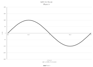
In the United States, that circuit is usually delivered to wall outlets and to datacenter PDUs as 120V 60Hz. This means that the voltage will cycle from positive 120V to negative 120V and back to positive 120V 60 times per second.
The voltage in this type of circuit is measured from hot-to-neutral, meaning the power is delivered on the “hot” connector and returned on an unpowered (or neutral) connector. So, with a 3-prong plug, one prong is hot, one prong is neutral, and one prong is ground.
The graph below shows the voltage for this type of circuit for a 1/60th of a second. (A sine wave has a period of 2π, and I have marked the x-axis with fractions of π for reference points.)
With commercial power, there are three phases – A, B, and C. Phase A has a phase shift of zero, phase B has a phase shift of 2π/3, and phase C has a phase shift of 4π/3. Here is a graph showing all three phases.
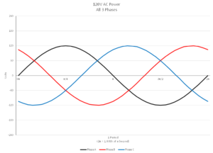
As a side note, even though it is not readily apparent from the graph, the sum of the voltage of all three phases is always zero.
208V Single Phase AC Circuits – United States
In the United States, commercial power frequently includes 208V single-phase circuits. With these circuits, the voltage is measured hot-to-hot; instead of from hot-to-neutral. So, with a 3-prong 208V plug, one prong is hot, the other prong is hot, and the third prong is ground. There is no neutral.
The same electrical panel that supplies 120V hot-to-neutral circuits can deliver 208V hot-to-hot circuits. If the diagram of all three 120V phases is redrawn with a few terminology changes, the result is…
Circuit breakers for 120V circuits occupy a single position with the electrical panel. Each position corresponds to an electrical bus for each power supply line. If you count the positions within a commercial electrical panel, the total will always be a multiple of three.
For a 208V single-phase circuit, a double-wide circuit breaker is required. This gives the circuit access to two different lines. Each line supplies 120V AC, and the two lines are phase shifted 2π/3 from each other. If we graph the voltage difference between Line 1 and Line 2, we get the following graph.
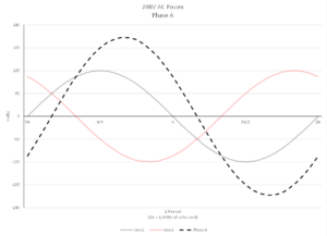
I’d like to point out a few features of this graph. The result is a 208V AC circuit, and voltage cycles from positive 208V to negative 208V and back to positive 208V, the pattern is a sine wave, and the period is 2π.
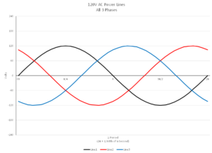
And here is the same graph showing all three 208V single-phase circuits – A, B, and C.
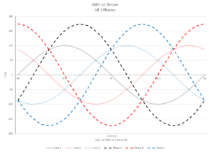
And as with the 120V circuits, the sum of the voltage of all three 208V phases is zero at every point on the graph.
208V 3-phase AC Circuits – United States
This type of circuit is less common than 120V and 208V single-phase circuits; however, it is still common. I most frequently encounter 208V 3-phase in high-density datacenters or in buildings with limited electrical panel space for new circuits.
For example, with a 208V 3-phase 30A PDU, the input power is 208V 3-phase, but the output power is three 208V single-phase 15A circuits. Put in terms of volt-amps, a 208V single-phase 30A PDU can supply 6240VA (208V*30A=6240VA), and a 208V 3-phase 30A PDU can supply 9360VA (3*208V*15A=9360VA). In a high-density datacenter, this allows 50% more volt-amps to be delivered from each PDU. Given the higher cost of 3-phase PDUs, UPSes, etc., many datacenters opt for 208V single-phase instead.
Delta vs. Wye
208V circuits can be delivered as either “delta” or “wye.” In simple terms, wye circuits include a line for neutral; delta does not. Most modern construction uses wye; however, delta still has its uses. For this reason, always check with a licensed electrician before purchasing 208V 3-phase equipment which specifies either delta or wye. For example, UPSes will usually specify either delta or wye and will only support that connection type. (And while it might be tempting to count the prongs on the plug (Delta is hot-hot-hot-ground, and wye is hot-hot-hot-neutral-ground), given the cost and lead time on that equipment that specifies delta or wye, I strongly recommend checking with an electrician first.)
230V AC Circuits – Most of Europe
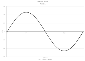
In most of Europe, the hot-to-neutral voltage is 230V 50Hz. Within the electrical panels, there will generally be three lines. (Line 1 will have a phase shift of 0, line 2 will have a phase shift of 2π/3, and line 3 will have a phase shift of 4π/3.) However, given that a 230V circuit supplies more voltamps than a 208V circuit with an equivalent amp rating, there is much less demand for hot-to-hot or 3-phase circuits in Europe than there is in the United States. This is especially true for datacenter equipment like servers, network switches, monitors, etc.
Below is a chart showing a the sine wave pattern for a 230V circuit.
Infrared Imaging of Electrical Panels???
There are a few warnings I issue to clients over and over again. You might recall my brief mention of a melted 400A bus bar earlier in this post. That event didn’t just shut down a datacenter. It shut down the entire building and severely damaged one of the rooftop air conditioning units. The generator could not be used. The melted bus bar was between the generator the building’s UPSes. All the UPSes fully discharged, and three production datacenters lost power. It was an expensive event.
That outage could have been avoided by regular infrared imaging studies of the electrical panels. After that incident, the electrical contractor was paid to use infrared cameras to examine all the electrical panels in the building. Those studies found where multiple circuits were physically warm because the sustained workload was too high (but not high enough to trip the circuit breaker). Many of those overworked circuits were on the same electrical phase. As a result, the bus bar for the entire building for that phase heated to the point of melting. And this could have all been prevented.
If you do not already have regularly scheduled infrared imaging of your electrical panels, please talk to your facilities department or your electrical contractor about scheduling it.
Conclusion
I hope you’ve enjoyed this blog post, and if not, I hope it has at least been educational. Electrical circuits are a frequent topic of conversation with clients, and so I hope this post will be useful to many people. Also, I will be referencing this post heavily in an upcoming blog post about how we size and organize electrical workloads in a datacenter.
And again, please consult with a licensed and bonded electrician (or master electrician) in your area when considering any changes to the electrical systems within your datacenters. The information in this blog post is no substitute for the expertise of trained and licensed electricians and master electricians.
This post is powered by Mix Digital Marketing