
Datacenter Electrical Power – An Overview (Part 2)
By Bill Jones, Enterprise Architect
Disclaimer
I am not a licensed electrician. Please consult with a licensed, bonded electrician or master electrician in your local area for assistance with electrical circuit or electrical system design.
Introduction
In my previous post on datacenter electrical power, we covered several basic subjects and a few advanced ones. This post will continue that discussion. As with the prior blog entry, my goal here is to provide information to help IT staff have more effective conversations with licensed, bonded electricians and with facilities staff.
Electrical Connectors
In modern datacenters, there are a multitude of available connector types. In this post I will be focusing on the connection types I encounter most frequently, which will be a subset of the International Electrotechnical Commission 60320 (IEC 60320) and National Electrical Manufacturers Association (NEMA) definitions. Just as electrical power can vary from country to country, so can the electrical connector type.
Male vs. Female Connectors
For the most part, referring to electrical connectors as male and female is much less common than it was a few years ago. And while it might be easy to assume that this change is driven by greater social awareness in the workplace, I think it has fallen out of use because it’s really easy to get the terms backwards with some connector types. In fact, the terms “male” and “female” have been dropped from many of the formal definitions for these connectors. Despite this, the terms are still used on the product description pages of a variety of products. So, for the sake of completeness, we will cover this topic.
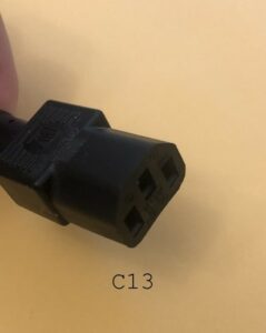
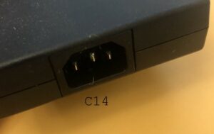
With electrical connectors, the conductive portion of the connector determines whether the connector is male or female. As an example, below are pictures of the power cord and power brick for my laptop’s docking station. The power cord uses an IEC 60320 C13 connector; the power brick uses an IEC 60320 C14 connector. Because the C14 connector has conductive prongs (or pins), it would be designated “male.” However, because the C13 connector inserts into the C14 connector, many people expect the C13 to be male. This mistake is very, very common. Referring to these connectors and C13 and C14 is clear and unambiguous. Referring to them as “male” and “female” readily causes confusion.
National Electrical Manufacturer’s Association (NEMA)
NEMA is the US-based organization which defines standards for electrical connectors. While many datacenters in the United States use NEMA style connectors, IEC 60320 connectors are much more commonly used. When a NEMA connector type ends with a “P,” that connector has conductive “pins” (or “prongs”). If the connector type ends with an “R,” that connector is the receptacle. (Personally, I think of the “P” and “R” and “plug” and “receptacle.”)
Below are the types of NEMA connectors I encounter most often in client datacenters
NEMA 5-15
If you live in the United States, this type of connector will be very familiar even if you don’t know its name. The electrical outlets in homes built in the last few decades are NEMA 5-15R. Growing up, we referred to these outlets as “3-prong outlets” to distinguish them from the older, ungrounded outlets.
In the 5-15, the “5” refers to a combined specification of the physical arrangement and shape of the conductors as well as a voltage rating. (5-15 connectors are rated for up to 125 volts.) The “15” indicates that the connector is rated for 15 amps.
With a 5-15P connector, there will be three conductors. Two will be parallel, vertical blades. The third will be a round pin.
NEMA 5-20
The 5-20 looks very similar to the 5-15. It has two blade-shaped prongs and a third, round prong for ground, and both 5-15 and 5-20 connectors are rated for 125 volts. However, with the 5-20P, the two blade-shaped conductors are not parallel; one blade is rotated 90 degrees.
The “20” in 5-20 indicates that the connector is rated for 20 amps. Rotating one of the conductive blades by 90 degrees helps to prevent connecting a device which requires a 20 amp circuit to an outlet only rated for 15 amps.
The 5-20R, on the other hand, has a T-shaped “slot” that allows it to receive either a 5-15P or 5-20P. I most often see 5-20R connectors in commercial buildings, especially as wall outlets within datacenters.
NEMA L6-30
The “L” designates a locking plug and locking receptacle. In the case of the L6-30, the lock is achieved by twisting the plug after it is inserted into the receptacle. The “locking” helps to prevent the plug from being accidentally unplugged. NEMA L6-30 connectors are used with 208V single-phase circuits, and the “30” indicates a rating of 30 amps. I most commonly encounter these with UPS (Uninterruptible Power Supply) connectors or with PDUs (Power Distribution Units).
International Electrotechnical Commission 60320
IEC 60320 defines the connector types which are most commonly used in datacenter electrical power. This is due to the widespread use of PDUs (Power Distribution Units). While you can order PDUs with in-country power receptacles, most clients opt for IEC 60320 receptacles (either C13 or C19). One of the big advantages to using IEC 60320 power connectors is that equipment can be moved between locations without needing to acquire new power cords. While buying new power cords usually requires minimal effort, it is still “one more thing” to deal with when relocating hardware. And, as one former manager of mine liked to say, “A ton of feathers still weighs a ton.” The second biggest advantage to IEC 60320 connectors is that the most commonly used connectors (C13, C14, C19, and C20) are rated for up to 250 volts. This allows them to be used for 120V, 208V single-phase, and 230V circuits. With in-country power cords (like NEMA) different connectors can be required for different voltage ratings.
IEC 60320 C13 and C14
These are the most common connector types in modern datacenters. The are also frequently used with computers we use in our homes. For example, the power cord for my laptop’s docking station is a specifically a NEMA 5-15P to IEC 60320 C13 power cord. My monitors use that same type of power cord, as do my Xbox and my Instant Pot. C13/C14 connectors are all over the place and are not just in datacenters.
C13/C14 connectors are rated for up to 15 amps in the US and for up to 12 amps almost everywhere else. (Please see my prior post for an explanation of the rating differences between countries.) C13 connectors feature three blade-shaped, parallel, vertical conductors in a triangular pattern. The non-conductive “chassis” for C13 connectors is hexagonal.
IEC 60320 C19 and C20
While C19/C20 connectors are less common than C13/C14, they are still in frequent use in datacenters, and PDUs are available with various combinations of C13 and C19 receptacles. The C19/C20 connectors are larger than C13/C14, and the three conductors are blade-shaped, parallel, and horizontal (whereas, the C13/C14 connectors are vertical). The non-conductive “chassis” for the C19 connector is rectangular. Also, C19/C20 connectors are rated for up to 20 amps.
How Do I Calculate the Electrical Requirement of My Datacenter?
Full disclosure: This section has been the goal of this series of blog posts. The prior blog post and the previous sections of this post have all been building to this topic. This is where we take all of these interconnected pieces of knowledge and create something that is definitely practical and possibly intricate and beautiful.
Step 1: Is This “Greenfield” or Are We Installing into Already Populated Environment?
If we are designing a net new configuration (i.e. racks are being purchased or are currently empty), we will want to spend some time looking at PDU (Power Distribution Options). If electrical circuits have not yet been run from the electrical panel to an outlet in the datacenter, we should also discuss the type of electrical circuit.
Uninterruptible POwer Supplies (UPSes)
Should you use a UPS? Yes. Absolutely, yes. Please, please, please, yes. UPSes not only protect devices from power loss, but they condition the power signal – smoothing out surges, providing a more consistent voltage, etc. This helps to prolong the life of the power supplies in devices.
If the datacenter already has a UPS for the entire room, great! Use that. (If the datacenter has both UPS and utility power options, please be certain you know which is which, and in these environments, I strongly encourage labeling power ports as UPS power or utility power.)
If the datacenter uses rack mounted or stand-alone UPSes to protect only specific devices, that’s fine, too.
Please do not cascade UPSes – for example, if the entire datacenter is on UPS, please don’t install rack-mounted UPSes in the datacenter to provide an “extra layer” of protection. The added value does not usually compensate for the added maintenance headaches. Room-sized UPSes are designed for routine maintenance, and facilities departments usually have contracts with electrical contractors to perform this work. Whereas, rack-mounted UPSes also require maintenance but that service is much more easily overlooked. As a result, if UPSes are cascaded, risk of failure will very often increase. So, please don’t do it.
To reduce costs, some clients opt to use UPS power for half of the power connections in the datacenter and utility power for the others. Since most devices have redundant power supplies, one can be connected to UPS power and the other to utility power. This allows the UPS to protect critical devices from power loss and avoids the cost of providing UPS protection for both sets of connections.
Transfer Switches
These are less frequently used devices, and they are often considered part of the facilities and electrical infrastructure than as a part of the IT infrastructure. A transfer switch is responsible for switching from one power source to another.
Many devices have redundant power supplies, but some devices (for example 1U Ethernet switches) may have only one power supply. In these cases, a transfer switch can be used to provide automatic failover between input power sources. Transfer switches often require that the input power signals be synchronized, but some do not. Synchronizing the power inputs can be complicated, so if you are interested in using a transfer switch to protect devices, please confirm whether the transfer switch will require synchronized inputs or not.
Power Distribution Units (PDUs)
PDUs are very common in datacenters, and many administrators continue to purchase what they purchased previously. There are lots of options when it comes to PDUs, so finding the “right” PDU standard for your datacenter may be difficult. I am a big fan of the maxim, “If you can’t be right, at least be consistent,” so choosing a simple PDU and continuing to buy the same type is very appealing. With that being said, I wouldn’t really be doing my job if I didn’t tell you what other options are out there.
What Is A Whip?
For a very long time, I thought PDUs used a power “WIP,” and I assumed WIP was an acronym. When I finally looked it up, I discovered that the term is “whip,” it is not an acronym, and it refers to the physical appearance of power cables with similar functions in modular furniture. When it comes to PDUs, the power whip refers to the cable which connects the PDU to its power source.
Managed, Monitored, or Basic?
Most of the clients I work with opt for basic (or unmonitored) PDUs. Some opt for monitored PDUs, and a few choose managed. Basic PDUs cost less than monitored and managed PDUs, and many ID admins are not involved with monitoring power consumption within the datacenter. Even with clients who have a facilities management team, facilities may not be interested in monitoring power at such a granular level. Basic PDUs may or may not include a circuit breaker or a fuse to protect against surges.
Monitored PDUs will report how power is being consumed. Depending on the model, the monitoring may be per port, per circuit, or for the whole PDU. Depending on the model, the monitoring may be via Ethernet or through a serial connection.
Managed PDUs allow administrators to toggle the power on specific ports. This can be very handy when the datacenter is at a remote location.
Horizontal or Vertical?
For 2-post racks, I tend to prefer horizontally mounted PDUs. I prefer to leave vertical space at the sides of the 2-post racks for cable management systems.
For 4-post racks, I prefer vertical PDUs. With vertical PDUs, power cable management is significantly easier and cleaner. This is especially true when there is sufficient space in the back of the rack for two vertical PDUs. (If the rack will have servers and if the servers will use cable management arms, I prefer to install both vertical PDUs on the same side of the enclosure. If cable management arms will not be used, I tend to prefer to mount one vertical PDU on each side and then use minimally long power cords.
With 4-post racks, sometimes there is insufficient room at the back of the enclosure for vertical PDUs. In those cases, horizontal PDUs should be used. When a horizontal PDU is installed at the back of the enclosure, please be sure not to use the corresponding PDU at the front of the enclosure. While it can be tempting to put a something with a short depth, the PDU at the back can easily obstruct the maintenance requirements of that device. Also, the space above and below the PDU get used, physical access to the device on the front of the rack will require removing a device from the rack.
How Many Amps?
The most common amperage I see for power whips in datacenters is 30 amps (based on US measurement, equivalent to 24A in most other regions). With 120V circuits, the whips are usually 20 amps. However, being the most common doesn’t mean it is the best option for your datacenter. Although, being the most common often means it will provide more options and may be available at a lower cost.
As a side note, I once ordered a 208V 3-phase 60A PDU because the electrical load of some equipment I was using could not be easily balanced across 208V single-phase 15A circuits. (208V 3-phase 30A PDUs usually split power into three 208V single-phase 15A circuits.) It was a costly endeavor. It required the electrician to run new cables to handle the 60A load, the connectors were massive and consumed significant wall space, and the PDUs themselves were relatively spendy. Unfortunately, when the PDUs arrived, I discovered that they did not split the 208V 3-phase 60A supply into three 208V single-phase 30A circuits. Instead, they split the supplied power into six 208V single-phase 15A circuits. I returned the PDUs, paid the electrician to run new 208V single-phase 30A circuits, and ordered new PDUs. Some life lessons are painful.
Step 2: What type of Electrical Circuits Will Be Used?
When we are sizing electrical circuits, we are ultimately talking about amps. The more amps flowing through a conductor, the more heat the current will generate. If too many amps flow through a conductor, the conductor can overheat. When a conductor overheats, components can become damaged, can fail, and can even catch on fire. And all of this comes back to amps.
Power consumption is measured in watts. Watts are calculated by multiplying voltage and amps, and this means that voltage has a very large impact on how we plan power requirements in a datacenter. For example, if a device consumes 200 watts of power, it would consume 1.7A at 120V, 0.96A at 208V, or 0.87A at 230V. Using a 208V circuit instead of 120V reduces the amperage by 42%.
Most devices built for datacenter use have “international” power supplies and can accept a wide range of input voltages and can also accept frequencies of 50-60 Hertz. But it is essential that you check each and every power supply. A little over 10 years ago, I converted a datacenter from 120V to 208V. I thought I had checked everything. The racks I was using included fans at the top of each rack to help evacuate the heater air. They were not rated for 208V, I did not check them in advance, and I fried the power supplies on those fans. On the bright side, the servers, storage, and networking were all fine.
As a final note on this topic, I am a big fan of 208V 3-phase, but not many people agree with me. Most of the clients I work with use 208V single-phase. And whether the circuit is 208V single-phase or 208V 3-phase will not impact amperage calculations.
Step 3: Doing the Math
The first time I tried to calculate power requirements as an IT administrator, I asked my electrician (Klaus) to help. I showed him a server and told him that according to the manufacturer’s power calculation tool, it could draw about 500W of power. Klaus then pointed to the two 800W power supplies in server. Klaus informed me that if he were to size the electrical circuits, he would calculate power based on both power supplies drawing full power at the same time (i.e. 1600W). Even though the manufacturer said the maximum draw was 500W total, his license and liability required him to size for 1600W. So, I asked Klaus a few other questions about sizing power circuits, thanked him for his time, and never discussed server power supplies with him again. By that I mean, I would tell him things like, “I have 4 servers which can each draw 2.5A at 208V,” instead of “I have 4 servers each with two 800W power supplies.”
To calculate power requirements for devices in the datacenter, we use multiple methods. First, many manufacturers offer power calculation tools that are very precise. For example, when calculating power for a rack mounted server, I can usually specify which processors, memory modules, drives, and add-on cards are included in the configuration and will get power ratings for both average consumption and for peak consumption. Second, when we don’t have power calculation tools for that device, we can frequently get that information from datasheets. Our third option is to work with the manufacturer to obtain the power consumption information. When those three options don’t work, we calculate based on the power supply wattage rating.
Another part of calculating power requirements for a datacenter is counting how many power receptacles are required to install new devices. For example, some devices I work with regularly can require a combination of C13/C14 and C19/C20 connectors. Checking to make sure there are sufficient power connectors of the required types is a vital part of installing new equipment. Afterall, it doesn’t help us much to have available amps on a circuit if we don’t have available receptacles on that circuit.
Step 4: Beware of Cascade Failures
Generally, a device with multiple power supplies will draw power through as few of its power supplies as possible. This is more efficient from a power process, and it reduces the wear and tear on the power supplies themselves. Some devices will distribute workloads evenly across the power supplies. Very rarely, I will encounter devices where different power supplies provide power to specific components, and with those devices, balancing power calculations with precision can be very complicated.
As an example of a cascade failure, let us suppose a server enclosure with two 208V single-phase 30A PDUs and twenty 1U servers. Each server has 2 power supplies, and at 208V, each server will draw 1.5A to 2.0A of power. This means that the enclosure could require up to 40A of current. With two PDUs, 60A of current is supplied, providing a maximum sustained load of 48A. If the servers draw their power evenly from both power supplies, we can connect one power supply from each server to each PDU, and that will put 20A of draw on each 30A PDU. Life is good… unless the circuit that feeds one of the PDUs loses power. Suddenly, the electrical current needs of all twenty servers will shift to a single 30A PDU. The minimum current draw is 30A, which exceeds the sustained workload design of 24A. Also, the odds are rather good that more than one of those servers is drawing more than 1.5A, which means the circuit breaker for that PDU will trip.
That is just one of many scenarios that can lead to a cascade failure, and cascade failures can be catastrophically bad. So, please, do what you can to avoid them in your design.
A Painful Lesson Learned
Many years ago, I was sitting at my desk when I saw the fluorescent lights in the building flicker. I thought to myself, “Huh. Brownout. I should check the server room.” As I walked to the server room, I realized how futile this was. The datacenter was protected by a UPS so large that there was a literal “UPS Room.” But, I continued to the server room because it seemed like the thing the senior IT admin should do. I opened the server room door, saw that everything looked okay, and let the door shut. As I watched the door slowly close, I realized something that prompted a wave of nausea and horror that I can still remember to this day. My server room was completely silent. This was my first professional lesson on the importance of managing datacenter power.
The short version of events was that several batteries in the UPS had failed. These would have been found during routine UPS maintenance, but we had not scheduled with anyone to perform that maintenance. When the brownout occurred, the failed batteries meant that the UPS could not power the datacenter. So, the UPS cut power to the datacenter until we manually switched the UPS to bypass. No one lost their jobs. The facilities manager was apologetic. Because I was local and the facilities manager was remote, it fell to me to explain to senior management why a small brownout caused nothing in the building to lose power except for everything that was on the UPS. Those were very uncomfortable conversations.
And so, while it can be easy for IT teams to think of electrical power as a facilities issue, I strongly recommend that you get to know your facilities management staff and your electricians. My career is more successful because of the things I learned from them. And, because we had an existing rapport, it made it easier for me to ask them questions when I didn’t understand things.
Conclusion
I hope this information is useful to you. Whether your datacenter is large or small, or even if your datacenter is a tower server under your desk, I believe that understanding how electrical power works within a datacenter is valuable to every IT admin. If you have any questions about how to understand datacenter power requirements, Dasher Technologies is here to help.
And again, please consult with a licensed and bonded electrician (or master electrician) in your area when considering any changes to the electrical systems within your datacenters. The information in this blog post is no substitute for the expertise of trained and licensed electricians and master electricians.
This post is powered by Mix Digital Marketing