
By Bill Jones, Senior Solution Architect
One of Dasher’s most popular blog posts of all time discusses the question, “Will Hyper-Threading Improve Processing Performance?” Bill Jones spent some time looking at the related topic of Intel Turbo Boost technology… get ready to really geek out to start 2017!
Intel Turbo Boost Technology 2.0 (hereafter “Turbo Boost”) is usually one of those features that administrators don’t think about. It is on by default, and unless they are actively monitoring CPU frequency on their systems, they probably have no idea whether Turbo Boost is helping their system performance or not. To better understand what Turbo Boost is, we’re going to need to spend some time talking about CPU clocks, overclocking, heat management, etc. In other words, there are a lot of underlying bits and pieces that make this whole thing work. Before we start our deep dive, let me share a quick overview of Turbo Boost.
Intel Turbo Boost Technology & Overclocking
Several years ago, overclocking home computers was a significant point of pride among technology enthusiasts – i.e. bragging rights among computer nerds. An overclocked CPU could execute instructions more quickly, but if heat wasn’t correctly managed the processor could overheat and cook itself. So, if you were going to overclock your home system, you had to have confidence that you were doing it correctly; otherwise, your very expensive computer could become a very expensive brick.
Then, along came Turbo Boost, which did several significant things. First, it provided intelligent, dynamic overclocking. This allowed the processor to stop overclocking if it became too warm. Once the processor cooled down, overclocking could resume. Thus the risk of overheating the processor was mitigated. Second, Turbo Boost allowed overclocking to move into the server arena – where the consequences of hardware failure are even higher.
So, with Turbo Boost enabled (which is, again, the default setting in modern BIOSes), the computer will automatically speed up and slow down the processor clock based upon heat (and other factors). In ordinary everyday use, this is a great benefit. However, when we get into heavy CPU load processes – like high performance compute (HPC) – frequent changes in CPU clock speed can actually interfere with system performance. If this happens, administrators have several options – such as limiting the maximum Turbo Boost frequency, reducing the number of active cores, or disabling Turbo Boost altogether.
(Intel Turbo Boost Max 3.0 is the latest version of Turbo Boost; however, it is currently only supported on a limited number of processors which are designed for mobile or desktop use. For this discussion, we will focus on Intel Turbo Boost 2.0, which is readily available in server, desktop, and mobile platforms.)
And so, with that being said, let’s dive deeper.
Why Do We Need a CPU Clock?
When working with hardware logic circuits, it takes time for each logic component to process its instructions. The time required varies slightly each time the process occurs and from component to component. As a result, there is a risk that the output value of a logic circuit can toggle between values while its components do their work. To help illustrate, below is a summary of the final lab from my first semester of my college digital logic class – which for reasons I won’t go into at this time, I still remember more than 20 years later.
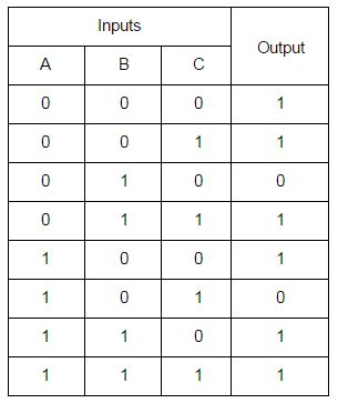
Below is the data table of input and output values.
Below is the circuit I designed for this set of inputs and outputs.
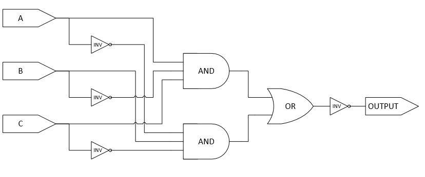
For those not familiar with logic circuit diagrams, I have added some text to help identify the elements. The symbols labeled “INV” are inverters. If they receive an input value of 1, they output a 0; if they receive a 0, they output a 1. The “AND” symbols will only output a 1 if all input values are 1. The “OR” will output a 1 if any of the input values are 1.Below is the circuit I designed for this set of inputs and outputs.
Because their impact is irrelevant for this example, we are going to assume that the all of the inverters and the OR gate take zero (0) nanoseconds (ns) to process. We are also going to assume that each AND gate takes between 750 ns and 1250 ns to process its inputs and – if necessary – change its output.
In this circuit, when A=1, B=0, and C=1 or when A=0, B=1, and C=0, the output will be 0. For all other inputs, the output will be 1. So, let’s see what happens when we switch between the two sets of values that produce a 0 output. For this test, we are going to assume that the top AND gate takes 800 ns to complete its processing, but the bottom AND gate takes 1200 ns. Prior to time zero (t=0), the inputs are A=1, B=0, and C=1. At t=0, we will instantaneously switch the inputs to A=0, B=1, and C=0.
At t<0:
- All inputs to the top AND gate are 1s, so its output is 1.
- One or more inputs to the bottom AND gate are 0s, so its output is 0.
- At least one input to the OR gate is 1, so its output is 1.
- The circuit’s output is 0 because the output of the OR gate is inverted to create the output.
At t=0:
- One or more inputs to the top AND gate are 0s. Its output will change from 1 to 0 in 800 ns.
- All inputs to the bottom AND gate are 1s. Its output will change from 0 to 1 in 1200 ns.
- At least one input to the OR gate is 1, so its output is 1.
- The circuit’s output is 0 because the output of the OR gate is inverted from 1 to 0.
At t=250:
- One or more inputs to the top AND gate are 0s. Its output will change from 1 to 0 in 550 ns.
- All inputs to the bottom AND gate are 1s. Its output will change from 0 to 1 in 950 ns.
- At least one input to the OR gate is 1, so its output is 1.
- The circuit’s output is 0 because the output of the OR gate is inverted from 1 to 0.
At t=500:
- One or more inputs to the top AND gate are 0s. Its output will change from 1 to 0 in 300 ns.
- All inputs to the bottom AND gate are 1s. Its output will change from 0 to 1 in 700 ns.
- At least one input to the OR gate is 1, so its output is 1.
- The circuit’s output is 0 because the output of the OR gate is inverted from 1 to 0.
At t=750:
- One or more inputs to the top AND gate are 0s. Its output will change from 1 to 0 in 50 ns.
- All inputs to the bottom AND gate are 1s. Its output will change from 0 to 1 in 450 ns.
- At least one input to the OR gate is 1, so its output is 1.
- The circuit’s output is 0 because the output of the OR gate is inverted from 1 to 0.
At t=1000:
- One or more inputs to the top AND gate are 0s, so its output is 0.
- All inputs to the bottom AND gate are 1s. Its output will change from 0 to 1 in 200 ns.
- All inputs to the OR gate are 0, so its output is 0.
- The circuit’s output is 1 because the output of the OR gate is inverted from 0 to 1.
At t=1250:
- One or more inputs to the top AND gate are 0s, so its output is 0.
- All inputs to the bottom AND gate are 1s, so its output is 1.
- At least one input to the OR gate is 1, so its output is 1.
- The circuit’s output is 0 because the output of the OR gate is inverted from 1 to 0.
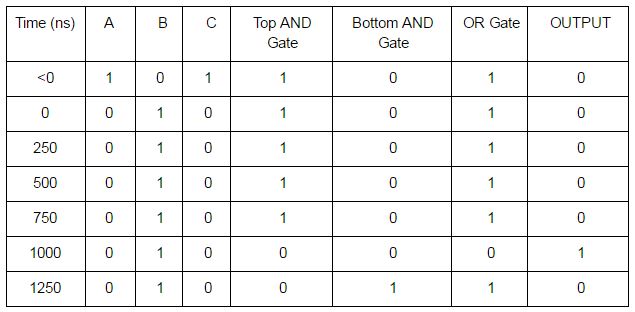 One way to address transient signals is to use a clock. Inputs are only allowed to change on clock cycles, and outputs are only read on clock cycles. Since our longest calculation time in this circuit is 1250 ns, a clock cycle of 1500 ns would ensure that transient signals are never read. A processor speed of 667 kHz (kilohertz) would result in a clock cycle of 1499 ns. As we can see, at 1000 nanoseconds (ns), the output of the circuit was 1, even though the inputs should have resulted in an output of 0. This incorrect output would have occurred from 800 ns to 1200 ns. After 1200 ns, the output would again be the correct value. This incorrect output is an example of a transient signal. Executing instructions based on this incorrect output could have catastrophic results.
In modern computing, CPU frequencies are usually measured in megahertz (MHz) or gigahertz (GHz). One (1) MHz is equal to one-million (1,000,000) cycles per second, and one (1) GHz is equal to one-thousand MHz – or 1,000,000,000 cycles per second. So, our circuit above would be very, very slow by today’s standards.
Why Does the Speed of Light Matter?
The speed of light is the fastest speed at which anything in our universe can travel. Light (in a vacuum) travels at this maximum speed – not because light creates the limit but because the limit prevents the light from traveling any faster. Electrons can travel at the speed of light, but they don’t like to travel in straight lines. Also, their speed can be reduced significantly by the medium through which they travel. The whole process is amazingly beautiful and complex at the same time. In college, my solid state physics class taught me – among other things – that I didn’t want to be an electrical engineer after all. As a result, we’re going to keep this section at a higher level.
The speed of light (in a vacuum) is about 300 million meters per second. One (1) gigahertz (GHz) is one-thousand-million cycles per second. Doing the math…
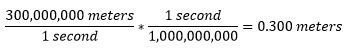
So, with a 1GHz clock, if the electrons were traveling in a straight line (which they don’t) through a vacuum (instead of copper or silicon), the maximum distance that an electron could travel between clock cycles is about 0.300 meters – or a little less than one foot. With faster clocks, the distance will be even shorter. (In most cases, with electrical signals we are dealing more with the propagation of the signal rather than the arrival of individual electrons. But at a high level, the same principles still apply.) So, even at the speed of light, distance matters. This is one of the major reasons why DIMM slots are so close to CPU connectors on motherboards.
Another example of where distance matters is in memory access. With the release of the Nehalem architecture, Intel moved the memory controller onto the processor’s silicon die (i.e. the socket). This changed multi-socket Intel computers from Uniform Memory Access systems to Non-Uniform Memory Access (NUMA). In a multi-socket system, when a core needs to access memory that is controlled by another socket, it makes the request over the QPI link between the sockets. Both the added distance and added components will increase the latency of this action. In NUMA systems, the main memory that is closest to the core (i.e. managed by the memory controller on the same socket as the core) is called “local memory.” Memory addresses managed by a controller on a different socket are “foreign memory” to that core. For a nice write-up on memory performance, please see: https://software.intel.com/en-us/articles/memory-performance-in-a-nutshell
Fortunately, modern operating systems know how to optimize instructions to take advantage of underlying processor architecture. They are aware of the different types and levels of processor cache, the locality of memory to specific cores, the impact of Intel Hyper-Threading Technology (HTT), etc.
So, even though it helps to be aware of these things, as administrators we don’t usually have to manage them. At least, not until we do.
What is Thermal Design Power (TDP)?
The specific definition for Thermal Design Power (TDP) varies slightly between manufacturers. In general, the TDP of a processor is the expected, maximum, sustained power draw from the processor when it is performing useful work. When we multiply watts by time, we get heat. For example, one watt-hour is equal to 3.41 BTUs. Thus, when processors draw more power, they will generate more heat over time.
Turbo Boost makes decisions based upon TDP. Depending on the processor’s’ temperature, power usage, and other factors, Turbo Boost may allow the processor to be overclocked. If the processor gets too warm or if the power is constrained, then overclocking gets reduced or stopped.
What are Enhanced Intel SpeedStep Technology, P-states, and C-states?
Enhanced Intel SpeedStep Technology (EIST) allows Intel processors to dynamically change their clock speed and voltage. Turbo Boost depends upon EIST (and other technologies) to function. Changing the clock speed and power conditions of the processor will change the amount of heat produced by the processor. It also provides optimizations for switching the clock speed of a core, etc. For more information on EIST, please see: http://www.intel.com/content/www/us/en/support/processors/000005723.html
P-states (or Performance States) are paired voltage and frequency values for the processor cores. By switching between P-states, the power consumption and heat production of the processor can be changed. Higher voltages and higher frequencies will consume more power and generate more heat.
C-states relate to how many cores on a processor are active. In C-state C0, all cores are active – i.e. zero (0) cores are inactive. To save power, idle or inactive cores can be powered down. As cores are powered down, the processor will enter higher C-state levels (C1-Cn).
For more information, on P-states and C-states, please see: https://itpeernetwork.intel.com/how-to-maximise-cpu-performance-for-the-oracle-database-on-linux/
Summary and Conclusion
In most cases, Turbo Boost is a very good thing. In most environments, it runs all the time without anyone even knowing it is there, occasionally boosting performance when heat and power conditions permit. Each adjustment briefly pauses CPU execution as the clock frequency is changed. If Turbo Boost adjusts system performance too frequently, system performance can be reduced. While this is rare, it does still occasionally occur.
Administrators have several tools for managing Intel Turbo Boost. Within the BIOS, administrators can limit the number of active cores. Administrators can also set a maximum Turbo Boost frequency within the BIOS. With lower core counts and/or lower CPU frequencies, the power consumption and heat generation of the processor can be reduced – which should reduce the rate at which Turbo Boost needs to adjust the CPU clock.
Please be aware, with fewer cores active, higher clock frequencies may become available. I recommend a careful review of the documentation for the relevant processor or processor family. Below are links to documentation for the Intel Xeon E5 v3 and v4 processor families:
- Intel Xeon E5 v3 – http://www.intel.com/content/dam/www/public/us/en/documents/specification-updates/xeon-e5-v3-spec-update.pdf
- Intel Xeon E5 v4 – http://www.intel.com/content/dam/www/public/us/en/documents/specification-updates/xeon-e5-v4-spec-update.pdf
When should administrators worry about managing their Turbo Boost settings? Some common examples include:
- High Performance Computing (HPC) applications will frequently have recommended settings for processor configurations – including Turbo Boost, Enhanced Intel SpeedStep Technology (EIST), Intel Hyper-Threading Technology (HTT), etc.
- Database servers can require careful optimization configuration, but in most cases, they won’t. There are very good reasons why research into Turbo Boost will lead to database administration discussions.
- XaaS providers frequently want to deliver optimal performance for their clients while managing infrastructure costs. Our clients in these areas sometimes need to manage Turbo Boost carefully to avoid performance issues. As their clients start and stop services, experience bursts in usage, etc., fully automated Turbo Boost can cause performance issues.
If you have further questions about Intel Turbo Boost 2.0 or how to better monitor it within your environment, we would be happy to continue the discussion.